
Page 288 - 2019 SHOP MANUAL CRF1000/A/D
P. 288
du
dummyheadmmyhead
DUAL CLUTCH TRANSMISSION (DCT) (CRF1000D)
3. CKP sensor Line Short Circuit Inspection
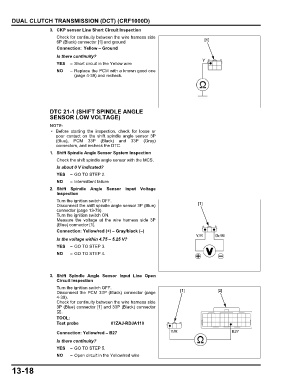
Check for continuity between the wire harness side
6P (Black) connector [1] and ground [1]
Connection: Yellow – Ground
Is there continuity?
Y
YES – Short circuit in the Yellow wire
NO – Replace the PCM with a known good one
(page 4-39) and recheck.
DTC 21-1 (SHIFT SPINDLE ANGLE
SENSOR LOW VOLTAGE)
• Before starting the inspection, check for loose or
poor contact on the shift spindle angle sensor 3P
(Blue), PCM 33P (Black) and 33P (Gray)
connectors, and recheck the DTC.
1. Shift Spindle Angle Sensor System Inspection
Check the shift spindle angle sensor with the MCS.
Is about 0 V indicated?
YES – GO TO STEP 2.
NO – Intermittent failure
2. Shift Spindle Angle Sensor Input Voltage
Inspection
Turn the ignition switch OFF.
Disconnect the shift spindle angle sensor 3P (Blue) [1]
connector (page 13-79).
Turn the ignition switch ON.
Measure the voltage at the wire harness side 3P
(Blue) connector [1].
Connection: Yellow/red (+) – Gray/black (–)
Y/R Gr/Bl
Is the voltage within 4.75 – 5.25 V?
YES – GO TO STEP 3.
NO – GO TO STEP 4.
3. Shift Spindle Angle Sensor Input Line Open
Circuit Inspection
Turn the ignition switch OFF.
Disconnect the PCM 33P (Black) connector (page [1] [2]
4-39).
Check for continuity between the wire harness side
3P (Blue) connector [1] and 33P (Black) connector
[2].
TOOL:
Test probe 07ZAJ-RDJA110
Connection: Yellow/red – B27 Y/R B27
Is there continuity?
YES – GO TO STEP 5.
NO – Open circuit in the Yellow/red wire
13-18