
Page 286 - 2019 SHOP MANUAL CRF1000/A/D
P. 286
du
dummyheadmmyhead
DUAL CLUTCH TRANSMISSION (DCT) (CRF1000D)
5. Clutch Line EOP Sensor Output Line Short
Circuit Inspection
Turn the ignition switch OFF.
Disconnect the PCM 33P (Blue) connector (page 4- [1]
39).
Check for continuity between the wire harness side
3P (Gray) connector [1] and ground.
Connection: Red/green – Ground
Is there continuity?
R/G
YES – Short circuit in the Red/green wire
NO – Replace the PCM with a known good one
(page 4-39) and recheck.
DTC 9-2 (CLUTCH LINE EOP SENSOR
HIGH VOLTAGE)
• Before starting the inspection, check for loose or
poor contact on the clutch line EOP sensor 3P
(Gray), PCM 33P (Black) and 33P (Gray)
connectors, and recheck the DTC.
1. Clutch Line EOP Sensor System Inspection
Check the clutch line EOP sensor with the MCS.
Is about 5 V indicated?
YES – GO TO STEP 2.
NO – Intermittent failure
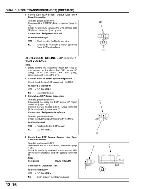
2. Clutch Line EOP Sensor Inspection
Turn the ignition switch OFF.
Disconnect the clutch line EOP sensor 3P (Gray) [1]
connector (page 13-80).
Connect the wire harness side 3P (Gray) connector
[1] terminals with a jumper wire [2].
Connection: Red/green – Gray/black
Turn the ignition switch ON.
Check the clutch line EOP sensor with the MCS. Gr/Bl R/G
Is 0 V indicated?
YES – Faulty clutch line EOP sensor
NO – GO TO STEP 3.
[2]
3. Clutch Line EOP Sensor Ground Line Open
Circuit Inspection
Turn the ignition switch OFF.
Disconnect the PCM 33P (Black) connector (page [1] [2]
4-39).
Check for continuity between the wire harness side
3P (Gray) connector [1] and 33P (Black) connector
[2].
TOOL:
Test probe 07ZAJ-RDJA110
Connection: Gray/black – B13 Gr/Bl B13
Is there continuity?
YES – GO TO STEP 4.
NO – Open circuit in the Gray/black wire
13-16