Page 287 - 2019 SHOP MANUAL CRF1000/A/D
P. 287

dummyheadmmyhead
             du

                                                             DUAL CLUTCH TRANSMISSION (DCT) (CRF1000D)
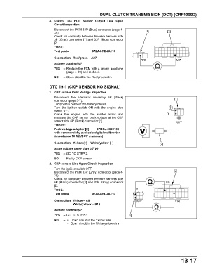
                               4. Clutch Line  EOP  Sensor Output Line  Open
                                 Circuit Inspection
                                 Disconnect the PCM 33P (Blue) connector (page 4-
                                 39).                                                   [1]          [2]
                                 Check for continuity between the wire harness side
                                 3P (Gray) connector [1] and 33P (Blue) connector
                                 [2].
                                 TOOL:
                                 Test probe             07ZAJ-RDJA110

                                 Connection: Red/green – A27
                                                                                     R/G                  A27
                                 Is there continuity?
                                 YES   – Replace the PCM with a known good one
                                         (page 4-39) and recheck.
                                 NO    – Open circuit in the Red/green wire

                               DTC 19-1 (CKP SENSOR NO SIGNAL)

                               1. CKP sensor Peak Voltage Inspection
                                 Disconnect the alternator assembly 6P (Black)
                                 connector (page 5-7).                                                   [1]
                                 Temporarily connect the battery cables.
                                 Turn the ignition switch  ON with the  engine stop
                                 switch " ".
                                 Crank the engine with the starter motor and                         Y
                                 measure the CKP sensor peak voltage at the CKP
                                 sensor side 6P (Black) connector [1].                                    W/Y
                                 TOOLS:
                                 Peak voltage adaptor [2]  07HGJ-0020100
                                 with commercially available digital multimeter
                                 (impedance 10 MΩ/DCV minimum)
                                 Connection: Yellow (+) – White/yellow (–)                      [2]
                                 Is the voltage more than 0.7 V?
                                 YES   – GO TO STEP 2.
                                 NO    – Faulty CKP sensor
                               2. CKP sensor Line Open Circuit Inspection
                                 Turn the ignition switch OFF.
                                 Disconnect the PCM 33P (Gray) connector (page 4-                        [2]
                                 39).
                                 Check for continuity between the wire harness side
                                 6P (Black) connector [1] and 33P (Gray) connector                  C8
                                 [2].
                                 TOOL:                                            Y
                                 Test probe             07ZAJ-RDJA110

                                 Connection: Yellow – C8                          W/Y                    C16
                                             White/yellow – C16
                                 Is there continuity?
                                 YES   – GO TO STEP 3.                        [1]
                                 NO    –  • Open circuit in the Yellow wire
                                          • Open circuit in the White/yellow wire


                                                                                                             13-17
   282   283   284   285   286   287   288   289   290   291   292