
Page 306 - 2019 SHOP MANUAL CRF1000/A/D
P. 306
du
dummyheadmmyhead
DUAL CLUTCH TRANSMISSION (DCT) (CRF1000D)
7. TR Sensor Inspection
Replace the TR sensor with a known good one
(page 13-79).
Connect the 3P (Black) connector, 33P (Black)
connector and 33P (Blue) connector.
Check the TR sensor with the MCS.
Is about 0 V indicated?
YES – Replace the PCM with a known good one
(page 4-39) and recheck.
NO – Faulty original TR sensor
DTC 51-2 (TR SENSOR HIGH
VOLTAGE)
1. TR Sensor System Inspection
Check the TR sensor with the MCS.
Is about 5 V indicated?
YES – GO TO STEP 2.
NO – Intermittent failure
2. TR Sensor Inspection
Replace the TR sensor with a known good one
(page 13-79).
Turn the ignition switch ON.
Check the TR sensor with the MCS.
Is about 5 V indicated?
YES – Replace the PCM with a known good one
(page 4-39) and recheck.
NO – Faulty original TR sensor
DTC 52-1 (NEUTRAL SWITCH STUCK
OFF)
• Before starting the inspection, check for loose or
poor contact on the neutral switch terminal and PCM
33P (Black) connector, and recheck the DTC.
1. DTC Recheck
Recheck the DTC with the MCS.
Is DTC 52-1 indicated?
YES – GO TO STEP 2.
NO – Intermittent failure
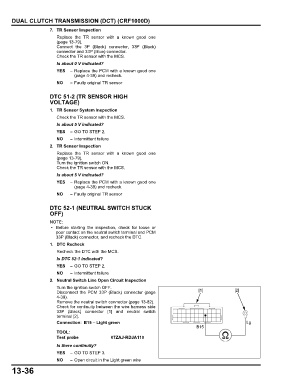
2. Neutral Switch Line Open Circuit Inspection
Turn the ignition switch OFF.
Disconnect the PCM 33P (Black) connector (page [1] [2]
4-39).
Remove the neutral switch connector (page 13-82).
Check for continuity between the wire harness side
33P (Black) connector [1] and neutral switch
terminal [2].
Connection: B15 – Light green Lg
B15
TOOL:
Test probe 07ZAJ-RDJA110
Is there continuity?
YES – GO TO STEP 3.
NO – Open circuit in the Light green wire
13-36