
Page 310 - 2019 SHOP MANUAL CRF1000/A/D
P. 310
du
dummyheadmmyhead
DUAL CLUTCH TRANSMISSION (DCT) (CRF1000D)
DTC 54-1 (OUTER MAINSHAFT
SENSOR SPEED LOW)
• Before starting the inspection, check for loose or
poor contact on the outer mainshaft sensor 3P
(Black), PCM 33P (Blue) and 33P (Black)
connectors, and recheck the DTC.
1. DTC Recheck
Erase the DTC (page 13-9).
Test-ride the motorcycle and stop the engine.
Check the DTC with the MCS.
Is DTC 54-1 indicated?
YES – GO TO STEP 2.
NO – Intermittent failure
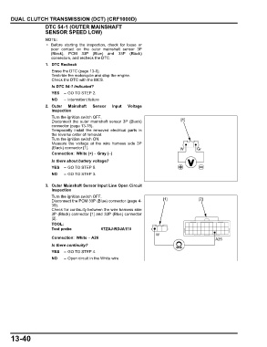
2. Outer Mainshaft Sensor Input Voltage
Inspection
Turn the ignition switch OFF.
Disconnect the outer mainshaft sensor 3P (Black) [1]
connector (page 13-78).
Temporarily install the removed electrical parts in
the reverse order of removal.
Turn the ignition switch ON.
Measure the voltage at the wire harness side 3P
(Black) connector [1]. W Gr
Connection: White (+) – Gray (–)
Is there about battery voltage?
YES – GO TO STEP 5.
NO – GO TO STEP 3.
3. Outer Mainshaft Sensor Input Line Open Circuit
Inspection
Turn the ignition switch OFF.
Disconnect the PCM 33P (Blue) connector (page 4- [1] [2]
39).
Check for continuity between the wire harness side
3P (Black) connector [1] and 33P (Blue) connector
[2].
TOOL:
Test probe 07ZAJ-RDJA110
W
Connection: White – A26 A26
Is there continuity?
YES – GO TO STEP 4.
NO – Open circuit in the White wire
13-40