
Page 312 - 2019 SHOP MANUAL CRF1000/A/D
P. 312
du
dummyheadmmyhead
DUAL CLUTCH TRANSMISSION (DCT) (CRF1000D)
7. Outer Mainshaft Sensor Output Line Short
Circuit Inspection
Check for continuity between the wire harness side
3P (Black) connector [1] and ground [1]
Connection: Pink – Ground
Is there continuity?
YES – Short circuit in the Pink wire
NO – Replace the PCM with a known good one P
(page 4-39) and recheck.
8. Outer Mainshaft Sensor Condition Inspection
Turn the ignition switch OFF.
Replace the outer mainshaft sensor with a known
good one (page 13-78).
Erase the DTC (page 13-9).
Test-ride the motorcycle and stop the engine.
Check the DTC with the MCS.
Is DTC 54-1 indicated?
YES – Replace the PCM with a known good one
(page 4-39) and recheck.
NO – Faulty original outer mainshaft sensor
DTC 55-1, 55-2 (No.1 LINEAR
SOLENOID VALVE)
• Before starting the inspection, check for loose or
poor contact on the linear solenoid valve 4P (Black)
and PCM 33P (Blue) connectors, and recheck the
DTC.
1. DTC Recheck
Recheck the DTC with the MCS.
Is DTC 55-1 or 55-2 indicated?
YES – GO TO STEP 2.
NO – Intermittent failure
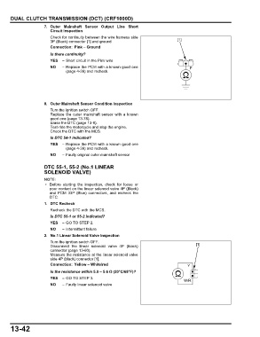
2. No.1 Linear Solenoid Valve Inspection
Turn the ignition switch OFF.
Disconnect the linear solenoid valve 4P (black) [1]
connector (page 13-60).
Measure the resistance at the linear solenoid valve
side 4P (black) connector [1].
Connection: Yellow – White/red Y
Is the resistance within 5.0 – 5.6 Ω (20°C/68°F)?
YES – GO TO STEP 3.
W/R
NO – Faulty linear solenoid valve
13-42