
Page 362 - 2019 SHOP MANUAL CRF1000/A/D
P. 362
dummyheadmmyhead
du
CRANKCASE/TRANSMISSION/BALANCER
Place the snap ring [1] onto the front balancer driven
gear assembly [2].
To prevent loss of Set the special tools onto the front balancer driven gear
spring tension, do assembly as shown and install the snap ring into the its
not compress the guide groove by compressing the friction spring. [3]
spring assembly TOOL:
more than
necessary. Clutch compressor set [3] 07LAE-PX40000
• Install the snap ring with the chamfered edge facing
opposite side of the washer and make sure that it is [2]
firmly seated in the groove.
Remove the special tools. [1]
INSTALLATION
Install the left front balancer bearing with the marked
side facing out. [4]
Install the right front balancer shaft/bearing assembly
[1]. [3]
Apply locking agent to the front balancer bearing set [2]
plate bolts threads (page 1-20).
Install the set plate [2] with its "OUTSIDE" mark [3] [4]
facing out.
Install the front balancer bearing set plate bolts [4] and
tighten them to the specified torque.
TORQUE:12 N·m (1.2 kgf·m, 9 lbf·ft)
Install the right crankcase cover. [1] [4]
– CRF1000/A (page 12-6)
– CRF1000D (page 13-55)
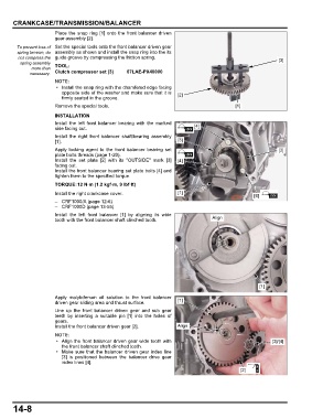
Install the left front balancer [1] by aligning its wide
tooth with the front balancer shaft clinched tooth. Align
[1]
Apply molybdenum oil solution to the front balancer
driven gear sliding area and thrust surface. [1]
Line up the front balancer driven gear and sub gear
teeth by inserting a suitable pin [1] into the holes of
gears.
Install the front balancer driven gear [2]. Align
• Align the front balancer driven gear wide tooth with [3]/[4]
the front balancer shaft clinched tooth.
• Make sure that the balancer driven gear index line
[3] is positioned between the balancer drive gear
index lines [4].
[2]
14-8