
Page 366 - 2019 SHOP MANUAL CRF1000/A/D
P. 366
dummyheadmmyhead
du
CRANKCASE/TRANSMISSION/BALANCER
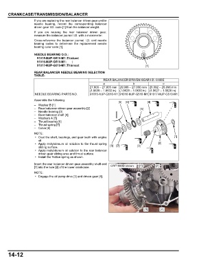
If you are replacing the rear balancer driven gear and/or
needle bearing, record the corresponding balancer
driven gear I.D. code [1] from the balancer weight.
If you are reusing the rear balancer driven gear,
measure the balancer journal I.D. with a micrometer.
Cross-reference the balancer journal I.D. and needle
bearing codes to determine the replacement needle
bearing color code [1].
NEEDLE BEARING O.D.:
91015-MJP-G510-M1:Thickest
91016-MJP-G510-M1:
91017-MJP-G510-M1:Thinnest [1]
REAR BALANCER NEEDLE BEARING SELECTION
TABLE:
REAR BALANCER DRIVEN GEAR I.D. CODE
a b c
27.000 – 27.005 mm 26.996 – 27.000 mm 26.992 – 26.996 mm
(1.0630 – 1.0632 in) (1.0628 – 1.0630 in) (1.0627 – 1.0628 in)
NEEDLE BEARING PARTS NO. 91015-MJP-G510-M1 91016-MJP-G510-M1 91017-MJP-G510-M1
Assemble the following:
[5] [6] [4]
–Washer B [1]
– Rear balancer driven gear assembly [2] [5]
– Needle bearing [3]
– Rear balancer shaft [4]
– Washers A [5]
– Thrust bearing [6]
– Thrust spring [7]
–Collar [8]
• Coat the shaft, bearings, and gear teeth with engine [1]
oil.
• Apply molybdenum oil solution to the thrust spring [2]
sliding surface. [8] [7] [3]
• Apply molybdenum oil solution to the rear balancer
driven gear sliding area and thrust surface.
• Install the friction spring as shown.
Insert the rear balancer driven gear assembly shaft end
[1] into the hole [2] of the lower crankcase. CRF1000D shown: [1] [2]
• Engage the oil pump drive [3] and driven gear [4].
[3] [4]
14-12