
Page 367 - 2019 SHOP MANUAL CRF1000/A/D
P. 367
dummyheadmmyhead
du
CRANKCASE/TRANSMISSION/BALANCER
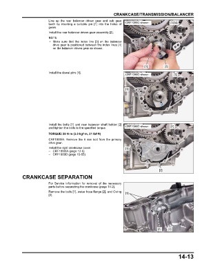
Line up the rear balancer driven gear and sub gear
teeth by inserting a suitable pin [1] into the holes of CRF1000D shown: [3]/[4]
gears.
Install the rear balancer driven gear assembly [2].
• Make sure that the index line [3] on the balancer
drive gear is positioned between the index lines [4]
on the balancer driven gear as shown.
[1] [2]
Install the dowel pins [1].
CRF1000D shown: [1]
[1]
Install the bolts [1] and rear balancer shaft holder [2]
and tighten the bolts to the specified torque. CRF1000D shown: [1]
TORQUE:29 N·m (3.0 kgf·m, 21 lbf·ft)
CRF1000/A: Remove the 6 mm bolt from the primary
drive gear.
Install the right crankcase cover. [1]
– CRF1000/A (page 12-6)
– CRF1000D (page 13-55)
[2]
CRANKCASE SEPARATION
For Service Information for removal of the necessary
parts before separating the crankcase (page 14-2).
Remove the bolts [1], water hose flange [2], and O-ring [1]
[3].
[3] [2]
14-13