Page 365 - 2019 SHOP MANUAL CRF1000/A/D
P. 365

dummyheadmmyhead
             du

                                                                      CRANKCASE/TRANSMISSION/BALANCER
                               INSPECTION
                               Inspect the following parts for  scratch,  damage,
                               abnormal wear, or deformation.
                               – Balancer driven gear
                               – Balancer sub driven gear
                               –Springs
                               – Balancer shaft
                               – Bearings
                               Replace if necessary.


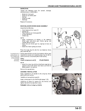
                               REAR BALANCER DRIVEN GEAR ASSEMBLY
                               Assemble the following:
                                                                                    [5]  [4]
                               – Rear balancer driven gear [1]
                               – Springs [2]
                               – Rear balancer sub driven gear [3]
                               – Friction spring [4]
                               –Washer [5]


                                • Apply  molybdenum oil solution to  the balancer
                                 driven gear, sub  driven gear, friction spring,  and
                                 washer sliding surface.
                                • Install the sub driven gear  by  aligning  its boss as                           [1]
                                 shown.
                                • Install the friction spring as shown.
                                                                                  [5]           [4]   [3]     [2]
                               Place the  snap ring [1] onto the  rear  balancer  driven
                               gear assembly [2].
                To prevent loss of  Set the special tools onto the front balancer driven gear
                spring tension, do  assembly as shown and install the snap ring into the its
                 not compress the  guide groove by compressing the friction spring.                                [3]
                 spring assembly  TOOL:
                      more than
                     necessary.  Clutch compressor set [3]  07LAE-PX40000

                                • Install the snap ring with the chamfered edge facing
                                 opposite side of the washer and make sure that it is  [2]
                                 firmly seated in the groove.
                               Remove the special tools.                                           [1]
                               ASSEMBLY/INSTALLATION
                               Apply molybdenum oil solution to the oil pump  driven
                               gear shaft outer surface.
                               Install the oil pump driven gear [1].
                               Apply locking agent to the bolt threads (page 1-20)  [3]/[4]
                               Install the set plate  [2], washer [3], and bolt [4] and                            [1]
                               tighten the bolt to the specified torque.
                               TORQUE:12 N·m (1.2 kgf·m, 9 lbf·ft)


                                                                             [2]


                                                                                                             14-11
   360   361   362   363   364   365   366   367   368   369   370