Page 319 - 2019 SHOP MANUAL CRF1000/A/D
P. 319

dummyheadmmyhead
             du

                                                             DUAL CLUTCH TRANSMISSION (DCT) (CRF1000D)
               A/M SWITCH TROUBLESHOOTING

                               If the engine can be started but AT/MT mode cannot be
                               changed, perform this troubleshooting.

                                • Before starting the inspection, check for loose or
                                 poor contact on the right handlebar switch and PCM
                                 33P connectors, and recheck the A/M switch
                                 operation.
                                • If the PCM is replaced, perform the Clutch Initialize
                                 Learning Procedure (page 13-82).
                               1. A/M switch Power Input Voltage Inspection
                                 Disconnect  the right handlebar switch  6P (Black)
                                 connector (page 22-24).                                [1]
                                 Turn the ignition switch  ON with  the  engine  stop
                                 switch " ".
                                 Measure the voltage between the wire harness side
                                 6P (Black) connector [1] and ground.                       Y/W
                                 Connection: Yellow/white (+) – Ground (–)
                                 Is there battery voltage?
                                 YES   – GO TO STEP 2.
                                 NO    – Open circuit in the Yellow/white wire
                                         between the right handlebar switch
                                         connector and fuse  box  (ENG STOP  7.5
                                         A)
                               2. A/M switch Inspection
                                 Turn the ignition switch OFF.
                                 Check for continuity at the switch side right     [1]
                                 handlebar switch 6P (Black) connector [1] in each
                                 switch position.                                                 Bl/W
                                 Connection: Black/white – Blue/black
                                 Is there continuity with the switch pushed and
                                 no continuity with the switch released?
                                 YES   – GO TO STEP 3.
                                 NO    – Faulty A/M switch
                                                                                                  Bu/Bl


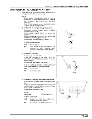
                               3. A/M switch Input Line Open Circuit Inspection
                                 Disconnect the PCM 33P (Blue) connector (page 4-
                                 39).                                        [1]                                   [2]
                                 Check for continuity between the wire harness side
                                 right handlebar switch 6P (Black) connector [1] and
                                 PCM 33P (Blue) connector [2].
                                 Connection: Blue/black – A17
                                 TOOL:
                                 Test probe             07ZAJ-RDJA110             Bu/Bl                  A17
                                 Is there continuity?
                                 YES   – Replace the PCM (page 4-39) with a
                                         known good one and recheck.
                                 NO    – Open circuit in the White/yellow wire


                                                                                                             13-49
   314   315   316   317   318   319   320   321   322   323   324