
Page 338 - 2019 SHOP MANUAL CRF1000/A/D
P. 338
du
dummyheadmmyhead
DUAL CLUTCH TRANSMISSION (DCT) (CRF1000D)
Coat new O-rings [1] with engine oil and install them
into the grooves in the primary driven gear [2]. [3]
Apply molybdenum oil solution to the primary driven
gear teeth, friction springs, and boss sliding area.
Install the clutch assemblies [3] onto the primary driven
gear.
[2] [1]
Apply engine oil to the needle bearings in the primary
driven gear.
• The primary driven gear has the index line [1] on its [2]
flange for the installation direction. The dual clutch [3]
assembly should be installed with the index line
facing the outside.
Line up the clutch disc tabs.
Install the washer [2] onto the clutch assembly.
Install clutch guide 1 [3] into the clutch on the index line
side by aligning the gear teeth with the clutch disc tabs.
[1]
Turn over the dual clutch assembly while holding clutch
guide 1.
Apply engine oil to the needle bearings in the primary
driven gear.
[1]
Line up the clutch disc tabs.
[2]
Install the washer [1] onto the clutch assembly.
Install clutch guide 2 [2] into the clutch by aligning the
gear teeth with the clutch disc tabs.
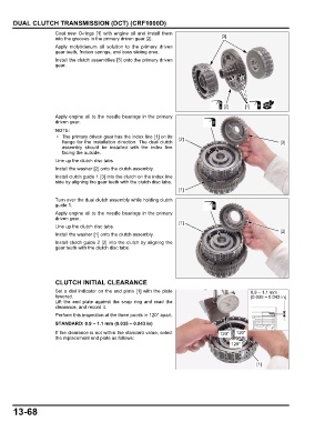
CLUTCH INITIAL CLEARANCE
Set a dial indicator on the end plate [1] with the plate 0.9 – 1.1 mm
lowered. (0.035 – 0.043 in)
Lift the end plate against the snap ring and read the
clearance, and record it.
Perform this inspection at the three points in 120° apart.
STANDARD: 0.9 – 1.1 mm (0.035 – 0.043 in)
If the clearance is not within the standard value, select 120° 120°
the replacement end plate as follows:
120°
[1]
13-68