
Page 475 - 2019 SHOP MANUAL CRF1000/A/D
P. 475
dummyheadmmyhead
du
HYDRAULIC BRAKE
DISASSEMBLY/ASSEMBLY
• When removing and installing the snap ring, use the
special tool.
TOOL:
Snap ring pliers 07914-SA50001
• Install the snap ring with the chamfered edge facing
the thrust load side and be certain it is firmly seated
in the groove. Do not reuse the snap ring which
could easily spin in the groove.
• Replace the piston, spring, and cup as a set.
• Do not allow the piston cup lips to turn inside out.
• Apply locking agent to the rear master cylinder hose
joint screw threads (page 1-20).
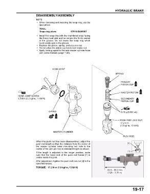
HOSE JOINT
SPRING
PRIMARY
PISTON CUP
MASTER PISTON
HOSE JOINT SCREW
1.5 N·m (0.2 kgf·m, 1.1 lbf·ft) SECONDARY
PISTON CUP
O-RING 0.10 g (0.004 oz)
PUSH ROD LOCK NUT
17.2 N·m
(1.8 kgf·m, 13 lbf·ft)
MASTER CYLINDER
PUSH ROD
When the push rod has been disassembled, adjust the
push rod length so that the distance from the center of [2]
the master cylinder lower mounting bolt hole to the
center of the joint pin hole is standard length as shown.
If the length is adjusted to the longer position, make [1]
sure that the lower end of the push rod thread [1] is
visible inside the joint.
After adjustment, tighten the push rod lock nut [2] to the
specified torque.
TORQUE: 17.2 N·m (1.8 kgf·m, 13 lbf·ft)
83.0 – 85.0 mm
(3.28 – 3.35 in)
19-17