
Page 472 - 2019 SHOP MANUAL CRF1000/A/D
P. 472
dummyheadmmyhead
du
HYDRAULIC BRAKE
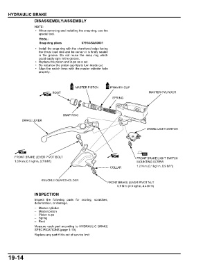
DISASSEMBLY/ASSEMBLY
• When removing and installing the snap ring, use the
special tool.
TOOL:
Snap ring pliers 07914-SA50001
• Install the snap ring with the chamfered edge facing
the thrust load side and be certain it is firmly seated
in the groove. Do not reuse the snap ring which
could easily spin in the groove.
• Replace the piston and cups as a set.
• Do not allow the piston cup lips to turn inside out.
• Align the switch boss with the master cylinder hole
properly.
MASTER PISTON PRIMARY CUP
BOOT MASTER CYLINDER
SPRING
SNAP RING
BRAKE LEVER
BRAKE LIGHT SWITCH
FRONT BRAKE LEVER PIVOT BOLT FRONT BRAKE LIGHT SWITCH
1.0 N·m (0.1 kgf·m, 0.7 lbf·ft) MOUNTING SCREW
COLLAR 1.2 N·m (0.1 kgf·m, 0.9 lbf·ft)
KNUCKLE GUARD HOLDER
FRONT BRAKE LEVER PIVOT NUT
5.9 N·m (0.6 kgf·m, 4.4 lbf·ft)
INSPECTION
Inspect the following parts for scoring, scratches,
deterioration, or damage.
– Master cylinder
– Master piston
– Piston cups
–Spring
– Boot
Measure each part according to HYDRAULIC BRAKE
SPECIFICATIONS (page 1-10).
Replace any part if it is out of service limit.
19-14